Breville BES920 — Technical Repair Dossier
240V/50Hz | Australia/NZ Region
This dossier was compiled with AI assistance from exploded diagrams, supplier part listings, and community repair knowledge. Resistance values, part codes, and wiring references are indicative only. Always verify against your specific unit's service manual or a known-good measurement before ordering parts or performing electrical work. Specifications may vary between production runs and regional variants. Work on mains-connected appliances carries risk of electrocution and fire — if in doubt, engage a licensed appliance repairer.
Machine Overview
| Attribute | Detail |
|---|---|
| Model numbers | BES920BSS (brushed stainless), BES920BKS (black sesame) |
| Voltage / Frequency | 240V / 50Hz (AU/NZ) |
| Power consumption | ~1700W |
| Boiler architecture | Dual boiler — independent brew boiler (PID) + steam boiler |
| Portafilter | 58mm commercial-style |
| Filter baskets | Dual wall (pressurised) and single wall (non-pressurised), multiple sizes |
| Water tank | 2.0L removable, compatible with Breville Claris water filter |
| Pump | ULKA vibratory pump |
| Temperature control | Independent PID for brew boiler; pressure stat / thermostat for steam boiler |
| Display | Digital LCD with brew temperature adjustment |
| Integrated grinder | No — separate grinder required |
| Country of sale | Australia, New Zealand |
How This Machine Differs from the BES870 and BES800ES
This comparison is critical if you're diagnosing a BES920 using BES870/BES800ES muscle memory — the architectures are fundamentally different.
| Feature | BES800ES / BES870 | BES920 |
|---|---|---|
| Thermal system | Single thermoblock | Dual boiler (brew + steam, independent) |
| Brew temperature control | Fixed or limited PID (thermoblock) | Full PID — user-adjustable brew boiler setpoint |
| Steam temperature control | Shared with brew path | Independent steam boiler with pressure stat |
| Heating elements | 1 × thermoblock element | 2 × elements (one per boiler) + cup warmer element |
| Temperature sensors | 1–2 NTC thermistors | 2 × NTC thermistors (one per boiler) + pressure stat |
| Solenoid valves | 1 × 3-way brew solenoid | 3-way brew solenoid + steam boiler solenoid |
| Flow meter | Not present (BES800ES) / present (BES870) | Present — critical for shot volume control |
| Pump | ULKA vibratory (shared part) | ULKA vibratory (shared part) |
| PCB complexity | Simpler | More complex — dual PID channels, more I/O |
| Integrated grinder | BES870: yes | No |
| Plumbing complexity | Simpler — fewer hose runs | More complex — two boiler feeds, check valves, more fittings |
| Failure complexity | Fewer failure points | More failure points; fault isolation requires identifying which boiler |
| Shot quality ceiling | Good | Higher — independent temperature control is the key advantage |
| Typical repair difficulty | Moderate | High — requires dual-boiler diagnosis methodology |
Service Menu & Temperature Diagnostics
Service Menu Reset / Clear Error & Descale Notifications
- With the machine off, hold 1 CUP and 2 CUP together for about 4 seconds.
- While holding them, press the POWER button to enter the service menu.
- The display should show
0000. - Press the UP button until the display shows
E RST(with the MANUAL button highlighted). - Hold the MANUAL button for a few seconds.
- This clears descale reminders and stored error-code notifications.
Temperature Diagnostics Menu
- Turn the machine off at the wall.
- Press and hold EXIT and MANUAL together.
- Turn the machine on at the wall while still holding the buttons.
- Press MENU until the display reads
LLLLorHHHH. - Press MENU + DOWN together to display the reported coffee temperature.
- Press MENU again to display the steam boiler temperature.
- Press MENU again to display the group head NTC reading.
Field-added service note: these button sequences were verified from hands-on use and are useful for clearing nuisance descale/error states and checking reported temperatures before disassembly.
1. Component Test Table
Test with the machine unplugged unless otherwise noted. Use a digital multimeter.
| Component | Location (Diagram Series) | Expected Resistance (cold / room temp) | Operating Voltage | Notes |
|---|---|---|---|---|
| ULKA EP5 main pump | Series 04 (04, 04.9) | ~1.1–1.3 MΩ pin-to-pin; Diode mode: ~0.79V forward, OL reverse (field-verified, 240V AU) | 240V AC | Internal diode blocks standard ohm readings — use diode test mode for definitive coil test. Hum without flow = blocked or seized. No hum = relay/PCB or wiring fault |
| ULKA NME boiler water pump | Series 05 area | ~1.2 MΩ pin-to-pin; Diode mode: ~1.6V forward, OL reverse (field-verified, 240V AU) | 240V AC | Higher diode-mode voltage than EP5 due to different coil impedance. Same diode testing applies |
| Group head heating element | Series 03 (group head) | ~286–300 Ω (~197W) (field-verified across BES920 + BES900) | 240V AC | Low wattage — maintains group head temp, not for boiling. Same part across BES900/920. Infinite = open element |
| Brew 3-way solenoid valve | Series 03 (03.x) | ~2.2–2.6 kΩ (coil) (field-verified, 240V AU) | 240V AC | Test coil resistance across terminals. Should read OL to ground on both pins. Mechanically stuck = no back-flush after shot |
| Brew boiler heating element | Series 03 (03.1–03.49) | ~77.6 Ω (~742W) (field-verified) | 240V AC | Infinite resistance = open circuit / failed element. Check element seal for leaks too |
| Steam boiler heating element | Series 05 (05, 05.4–05.25) | ~47.7 Ω (~1208W) (field-verified) | 240V AC | Lower resistance = higher wattage — steam boiler needs more power to reach/maintain steam pressure. Failure usually presents as no steam / weak steam |
| Brew NTC thermistor | Series 03 (brew boiler area) | ~10 kΩ at 25°C; ~2–3 kΩ at 80°C | Signal voltage (3.3V or 5V DC) | Shorted NTC → PID sees overtemp, no heat. Open NTC → PID sees undertemp, may overheat |
| Steam NTC thermistor / pressure stat | Series 05 (05.4–05.25) | NTC: ~10 kΩ at 25°C; Pressure stat: continuity below setpoint | Signal / 240V AC | Pressure stat should show continuity when boiler is cold (unpressurised) |
| Thermostat | Near boiler | ~0.1 Ω (continuity) (field-verified) | 240V AC | Should pass continuity when cold. Open = failed thermostat |
| Thermal fuse — brew boiler | Series 03 (near element) | ~0.4 Ω (continuity) (field-verified) | One-shot, 240V AC | Blown fuse (OL/infinite) = open circuit. Non-resettable. Indicates prior overtemp event — find root cause |
| Thermal fuse — steam boiler | Series 05 (near element) | ~0.4 Ω (continuity) | One-shot, 240V AC | Same as above. Both boilers have independent fuses |
| Flow meter | Series 06 (06.6–06.67) | N/A (Hall effect sensor) | 5V DC signal | Test with machine powered: 5V supply to sensor, pulsed output during water flow. No pulses = failed sensor or blocked impeller |
| PCB mains fuse | Series 02 (PCB assembly) | 0 Ω (continuity) | 240V AC protection | Usually a ceramic cartridge fuse. Blown fuse with no obvious cause → check for shorted element or pump |
| Cup warmer element | Series 01 (01.28) | 1–5 kΩ (lower power element) | 240V AC | Rarely fails; check if cup warmer completely non-functional |
2. Dual Boiler Logic — How It Works
Architecture Overview
The BES920 contains two completely independent thermal circuits sharing one pump and one water supply:
-
Brew boiler (Series 03): A small-volume boiler dedicated solely to producing brew-temperature water (typically 90–96°C). It is PID-controlled — the PCB reads a NTC thermistor in the brew boiler and switches the brew heating element on/off to maintain the user-set temperature with high precision.
-
Steam boiler (Series 05): A larger-volume boiler that operates at steam pressure (typically 120–130°C, ~1.5–2 bar). It is controlled by a pressure stat (or NTC + pressure sensor) rather than a direct PID loop. The steam boiler maintains pressure within a band; the heating element cycles on when pressure drops below the lower threshold.
Independent Operation
Both boilers can heat simultaneously. When you power on the machine, both boilers begin heating in parallel. The brew boiler reaches its setpoint first (it's smaller and runs at lower temperature). The steam boiler takes longer to reach steam pressure.
The digital display shows brew boiler temperature during warmup. A separate steam-ready indicator shows when the steam boiler has reached operating pressure.
Startup Sequence
- Power on → PCB initialises, both boiler heating elements energise
- Brew boiler heats rapidly to PID setpoint (typically 2–5 minutes depending on thermal mass)
- Brew-ready indicator activates when brew boiler NTC reads within range of setpoint
- Steam boiler continues heating toward pressure stat cutout point
- Steam-ready indicator activates when steam pressure reaches operating threshold
- Machine is now fully operational — brew circuit and steam circuit are thermally independent
Shot Delivery Sequence
- User initiates shot → PCB activates pump (Series 04) and opens brew solenoid (Series 03)
- Flow meter (Series 06) counts pulses as water passes through
- Water from pump enters brew boiler, exits at brew temperature through group head
- At target volume (pulse count), PCB deactivates pump and de-energises solenoid
- 3-way solenoid redirects residual pressure to drip tray (back-flush)
- Brew boiler PID continues regulating temperature between shots
Why This Matters for Diagnosis
Because the two boilers are independent, you can isolate faults:
- Shot cold but steam fine → brew boiler fault (element, NTC, or PID channel)
- No steam but shot temperature correct → steam boiler fault (element, pressure stat, or wiring)
- Both circuits dead → likely mains input, PCB fuse, or main PCB fault
3. Circuit Topography
PCB Assembly (Series 02: 02, 02.4, 02.6, 02.8, 02.31, 02.32)
The main PCB handles: mains input switching, both boiler element relays, pump relay, solenoid drivers, flow meter signal input, both NTC thermistor ADC inputs, display output, and user button inputs.
⚠️ Testing Ulka Pumps — Diode Mode Required
Both the EP5 (main brew pump) and NME (boiler water pump) have an internal 1N4007 diode in series with the coil. A standard multimeter in resistance mode outputs only ~0.2–0.5V — insufficient to forward-bias the diode (~0.7V threshold). This means:
- Resistance mode: You'll see ~1–1.3 MΩ in one direction and OL in the other. This is normal — it's diode leakage, not coil resistance.
- Diode test mode: Pushes ~3V, enough to overcome the diode. This is the correct way to test pump coils.
- Healthy EP5: ~0.79V forward, OL reverse
- Healthy NME: ~1.6V forward, OL reverse (higher due to different coil impedance)
- Dead coil: OL in both directions
Do not condemn a pump based on megaohm readings in resistance mode — always confirm with diode test.
Ulka Pump Condition Table (Diode Mode — 240V AU)
Use these field-verified readings to assess pump health. All readings taken with multimeter in diode test mode.
| Pump | Condition | Diode Mode (Forward) | Resistance Mode | Verdict |
|---|---|---|---|---|
| EP5 | Healthy (new) | ~0.79V | ~1.1–1.3 MΩ | ✅ Good — replace if other symptoms point to pump |
| EP5 | Degraded | ~1.35V | ~7.7 MΩ | ⚠️ Winding breakdown — may buzz/run but won't deliver full pressure. Replace coil |
| EP5 | Dead (open) | OL both directions | OL | ❌ Open winding — no function |
| EP5 | Dead (shorted diode) | ~0V or very low both directions | Low Ω both directions | ❌ Diode failed short — pump may buzz but won't pump |
| NME | Healthy | ~1.6V | ~1.2 MΩ | ✅ Good — higher diode-mode voltage is normal (higher-impedance coil, lower wattage) |
| NME | Dead (open) | OL both directions | OL | ❌ Open winding — no function |
How to read the table: A healthy EP5 shows ~0.7V diode drop + minimal coil voltage. The NME reads higher (~1.6V) because its smaller, lower-wattage coil has higher resistance — more voltage drops across the winding during diode test. If an EP5 reads significantly above ~0.8V (e.g. 1.35V), the extra voltage is from degraded winding resistance — the pump is failing even if it still runs.
All pumps should read OL in reverse — any reverse reading indicates a failed diode.
Test Points by Symptom
No power (display dead, no heating)
- Check mains cord and plug (Series 09, 09.17/09.18)
- Check PCB mains fuse (Series 02) — locate ceramic fuse on PCB input stage
- Measure mains voltage at PCB input terminals (240V AC expected) — requires caution, machine plugged in
- If fuse blown repeatedly: suspect shorted element (test both heating elements for isolation to chassis)
Brew boiler not heating (display shows brew temp stuck at ambient)
- Confirm display shows brew NTC reading (not frozen/error code)
- Test brew NTC thermistor: disconnect from PCB, measure resistance, compare to temperature curve (~10 kΩ at 25°C)
- Test brew heating element for continuity (unplug machine)
- Test brew thermal fuse continuity (in series with element circuit)
- Check relay output on PCB: with machine powered and brew boiler below setpoint, relay should energise (audible click, 240V AC across element terminals)
Steam boiler not heating (no steam, steam pressure gauge low)
- Test steam heating element resistance and thermal fuse (same method as brew boiler)
- Test pressure stat / steam NTC: should show continuity / expected resistance when cold
- Check steam boiler relay on PCB: should energise when steam pressure below setpoint
Pump not activating (no water flow on shot)
- Confirm pump receives 240V AC during shot initiation (requires powered test — caution)
- Test pump coil resistance (~1.1–1.3 MΩ pin-to-pin expected)
- Check pump relay on PCB
- Inspect flow meter signal wire — PCB may suppress pump if flow meter shows fault condition
Display / PID fault (error codes, frozen display, erratic temperature)
- Check display module connector (Series 02 display cable, 02.31/02.32)
- Inspect NTC wiring for damage or disconnection
- A shorted NTC will cause the PID to see max temperature and refuse to heat — check NTC resistance
- An open-circuit NTC will cause temperature runaway on some firmware versions
4. Common Failure Points
Ranked by observed frequency in AU repair community:
| Rank | Failure | Boiler Affected | Symptoms | Diagnosis |
|---|---|---|---|---|
| 1 | Brew boiler scale buildup | Brew | Shot temperature unstable, slow to reach setpoint, reduced flow | Descale cycle; inspect element for scale jacket |
| 2 | 3-way brew solenoid valve failure | Brew | No back-flush after shot, coffee grounds in drip tray, pressure retained in portafilter | Test solenoid coil resistance; inspect valve seat for debris |
| 3 | Brew NTC thermistor failure | Brew | PID shows error / ambient temp / runaway | Test thermistor resistance vs temperature curve |
| 4 | Brew heating element failure | Brew | Shot cold, brew boiler won't reach setpoint, element OL on meter | Test resistance; check thermal fuse in series |
| 5 | Steam heating element failure | Steam | No steam or very weak steam, steam boiler cold | Test resistance; check thermal fuse in series |
| 6 | Flow meter failure | Both (pump control) | Pump runs indefinitely, shot volume inconsistent, machine won't stop shot | Check Hall effect sensor supply voltage and pulse output |
| 7 | Steam boiler pressure stat failure | Steam | Steam boiler overheats / cycles incorrectly / safety valve venting | Test pressure stat continuity at ambient (should be closed) |
| 8 | PCB / relay failure | Either or both | One or both boilers not heating despite good elements, pump not activating | Board-level diagnosis; check relays for burn marks or failed contacts |
Note on dual-element failure sequencing: The brew boiler element is under more thermal stress (rapid heat-cool cycles per shot) while the steam boiler element runs more continuously but at lower relative load. Brew boiler element or its NTC tends to fail first in heavily used machines.
5. Diagnostic Trees
Tree A: Brew Boiler Not Reaching Temperature (Shot Too Cold)
Shot is cold / PID setpoint not reached
│
├─ Is the display showing a temperature reading?
│   ├─ NO / Error code → NTC thermistor fault (open or shorted)
│   │   └─ Test brew NTC resistance → replace if out of spec
│   │
│   └─ YES (temp stuck at ambient or climbing slowly)
│       │
│       ├─ Does temp rise at all during warm-up?
│       │   ├─ NO → Element or thermal fuse open
│       │   │   ├─ Test brew heating element resistance (expect 30–80 Ω)
│       │   │   ├─ OL result → replace element
│       │   │   └─ Good element → test thermal fuse continuity → replace if blown
│       │   │       (also find root cause of overtemp event)
│       │   │
│       │   └─ YES (rises but slowly / never reaches setpoint)
│       │       ├─ Heavy scale on element → descale, inspect element
│       │       ├─ NTC reading low (element heating but PID under-reading) → test NTC
│       │       └─ Partial element failure → test resistance (should be ~uniform)
│       │
│       └─ Temp reaches setpoint but shot still cold?
│           └─ Group head heat loss → check pre-infusion / idle time
│               or shower screen/dispersion block scale
Tree B: Steam Pressure Weak / Steam Boiler Fault
Weak or no steam
│
├─ Does steam boiler heat at all? (feel housing after 10 min)
│   ├─ Cold → No power to steam boiler
│   │   ├─ Test steam element resistance
│   │   │   ├─ OL → failed element → replace
│   │   │   └─ Good → test thermal fuse in series → replace if blown
│   │   └─ Both good → check PCB steam relay / wiring
│   │
│   └─ Warm but low pressure
│       ├─ Scale on steam boiler element → reduced heat transfer → descale
│       ├─ Pressure stat set too low or failed → test continuity cold
│       │   └─ Stat stays open when cold → failed → replace
│       ├─ Steam boiler safety valve weeping → steam escaping before full pressure
│       └─ Steam wand blocked → clear wand tip and steam valve (Series 09)
│
└─ Steam fine but hot water output weak?
    └─ Hot water solenoid / valve issue (Series 09.21 hot water wand comp)
Tree C: Machine Trips RCD on Power-On
RCD trips immediately or within seconds of power-on
│
├─ Trips instantly on power-on
│   ├─ Disconnect steam boiler element → re-test
│   │   ├─ RCD holds → steam element shorted to chassis → replace element + check element seal
│   │   └─ Still trips → disconnect brew boiler element → re-test
│   │       ├─ RCD holds → brew element shorted → replace + check seal
│   │       └─ Still trips → pump or PCB shorting → isolate and test
│   │
│   └─ Note: test each element for chassis continuity with multimeter
│       (any reading from element terminal to chassis ground = fault)
│
├─ Trips after ~30–60 seconds (warm trip)
│   ├─ Element seal failure — water tracking to chassis
│   │   └─ Inspect both element seals / O-rings for cracks or weeping
│   └─ Thermal fuse holder tracking when hot → inspect insulation
│
└─ Trips only during steam use
    └─ Steam element insulation breakdown at temperature → replace steam element
6. Exploded Diagrams & Resources
Diagram 1 — External Housing, Panels, User-Facing Components
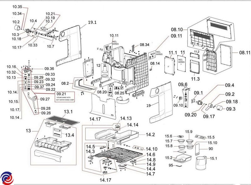
Key series:
- 08 — Rear panel, back housing, ventilation grille, electrical covers
- 09 — Steam wand, hot water wand comp (09.21), steam valve, seals, fittings, power cord entry (09.17 / 09.18)
- 10 — Top panel, cup-warming tray, side panels, brackets
- 11 — Control electronics / display panel, PCB enclosures (incl. wires)
- 12 — Internal frame / chassis
- 13 — Drip tray assembly (13, 13.1, 13.4)
- 14 — Group head area, brew platform, portafilter rest (14.1–14.17)
- 15 — Portafilter, filter baskets (single/dual wall), tamper, accessories (15.1–15.10)
Diagram 2 — Internal Mechanisms, Boilers, Pump, Hydraulics, Electronics
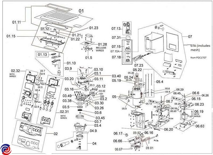
Key series:
- 01 — Cup-warming tray heating element (01.28 incl. wires), brackets
- 02 — Main control PCB assembly (02, 02.4, 02.6, 02.8, 02.31, 02.32 with wires), display module, buttons
- 03 — Brew boiler, heating element, group head, shower screen, gaskets, 3-way solenoid valve, dispersion block, seals (03.1–03.49)
- 04 — Pump assembly and mounting hardware (04, 04.9)
- 05 — Steam boiler, heating element, pressure stat/sensor, safety valve, fittings (05, 05.4–05.25)
- 06 — Base frame, hydraulic plumbing, flow meter, check valves, hose connections (06.6–06.67)
- 07 — Water tank, housing/cradle (07A incl. mesh from PDC1707), lid, tank connection valve/seal (07, 07A, 07.13–07.31)
Diagram 3 — Claris Filter Assembly
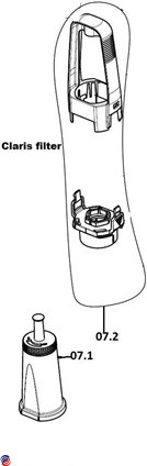
- 07.1 — Claris filter cartridge
- 07.2 — Filter holder / adapter
Source: Appliance Supplies AU — BES920BKS parts listing
Confirmed Part Codes
BES920-specific parts:
| Code | Notes |
|---|---|
| BES9200128 | BES920-specific component |
| BES9200232 | BES920-specific component |
| BES920031 | BES920-specific component |
| BES9200345 | BES920-specific component |
Shared / variant codes (BES900-series, may apply to BES920):
| Code | Code | Code | Code |
|---|---|---|---|
| BES9000123 | BES9000231 | BES900028 | BES9000311 |
| BES9000321 | BES9000326 | BES9000338 | BES9000342 |
| BES9000349 | BES9000513 | BES900056 | BES900059 |
| BES9000619 | BES9000620 | BES9000626 | BES900066 |
| BES9000723 | BES9000927 | BES9000928 | BES9000937 |
| BES9001015 | BES9001510 | BES900155 | BES900156 |
| BES900157 | BES900159 |
SP-series confirmed codes:
| Code | Notes |
|---|---|
| SP0001634 | Confirmed for BES920 |
| SP0001695 | Confirmed for BES920 |
Always confirm part applicability to your specific model variant (BES920BSS vs BES920BKS) and production date before ordering. Part numbers may differ between AU and international variants.
7. Manual & Resource Search Strings
Use these exact strings in search engines, iFixit, and YouTube:
Breville BES920 service manual
Breville BES920 repair guide
BES920BSS disassembly
BES920 dual boiler element replacement
BES920 flow meter replacement
BES920 brew boiler scale descale
BES920 NTC thermistor replacement
BES920 3-way solenoid valve repair
BES920 PID temperature calibration
BES920 no steam fault
BES920 RCD trip fault
"BES920" site:home-barista.com
"BES920" site:coffeegeek.com
"BES920" filetype:pdf service
Breville dual boiler espresso repair AU
BES900 series repair
Parts suppliers (AU/NZ):
- Appliance Supplies AU
- Breville Spare Parts AU
- Espresso Parts AU
- eBay AU — search
BES920 partsor specific part codes
8. Known Quirks & Gotchas
PDC1707 Water Tank Housing Change (07A)
A running production change introduced a revised water tank cradle/housing (part reference 07A, incorporating mesh from PDC1707). Units with this change use different tank seals from earlier production. If ordering tank seals or the tank connection valve/seal assembly, check your machine's production date code. Using the wrong seal can result in slow tank leaks that are easy to miss until water tracks to electrical components.
Scale Builds Faster in the Brew Boiler
The brew boiler is significantly smaller volume than the steam boiler. With the same water hardness, it will scale up proportionally faster. Descale cycles treat both boilers, but in hard water areas the brew boiler should be the primary concern. Signs: brew temperature instability, PID cycling more frequently, reduced flow rate. Do not skip descaling — heavy scale can thermally insulate the element and cause thermal fuse failure.
PID Calibration Drift
The brew boiler PID setpoint can drift over time, particularly after PCB or NTC replacement. If shots taste different at the same grind/dose and the display shows the usual setpoint, the NTC may be reading slightly high or low. Cross-check actual brew boiler temperature (if possible) against the displayed value. Some users offset the setpoint by 1–2°C after NTC replacement to account for sensor variance.
Dual Element Failure Sequencing
The brew boiler element is subject to more thermal cycling stress (heats and cools with each shot cycle) while the steam boiler element runs more continuously but at a more stable temperature. In practice, the brew boiler element or its NTC tends to fail first in high-use machines. If you're preemptively servicing a heavily used BES920, prioritise checking the brew boiler circuit first.
Check Which Boiler Is Faulty Before Disassembly
Before pulling the machine apart, use the symptom table:
- Cold shots + normal steam → brew circuit fault → focus on Series 03 / brew boiler
- Normal shots + no steam → steam circuit fault → focus on Series 05
- Both circuits dead → PCB/power fault → focus on Series 02
Identifying the faulty boiler first saves significant disassembly time — the two boiler assemblies are in different areas of the chassis and require different access paths.
Steam Boiler Safety Valve Weeping
If you hear intermittent hissing from the rear of the machine during steam operation, the steam boiler safety valve (Series 05) may be weeping. This is sometimes caused by scale debris partially holding the valve open rather than true valve failure. A descale cycle may resolve it; if not, the safety valve is a replaceable item.
Flow Meter — Debris Sensitivity
The flow meter impeller (Series 06) is sensitive to debris. If a silicone hose fragment, scale chip, or assembly residue enters the flow path, the impeller can jam or spin erratically, causing the PCB to miscount shot volume. Symptom: shot volume becomes inconsistent or the pump runs too long / stops too early. Disassemble and inspect the flow meter impeller chamber before condemning the sensor electronics.
9. Cross-References
Shared Components with BES870
These parts are believed to be shared between the BES920 and BES870 (verify before ordering — Breville sometimes uses visually identical but dimensionally different parts across model lines):
| Component | Series | Notes |
|---|---|---|
| ULKA pump body | Series 04 | Same pump family; verify mounting bracket and hose fitting dimensions |
| 3-way brew solenoid valve | Series 03 | Same solenoid coil resistance range; valve body may differ |
| Group head gasket | Series 03 | 58mm portafilter gasket — same spec, likely shared |
| Shower screen | Series 03 | 58mm, likely shared across BES900-series |
| Portafilter and baskets | Series 15 | 58mm system — accessories are shared across the range |
| Drip tray assembly | Series 13 | Check dimensions — may differ between models |
Components That Do NOT Transfer Between BES870 and BES920
| Component | Reason |
|---|---|
| Brew boiler assembly | BES920 has a dedicated brew boiler vessel; BES870 uses a thermoblock — fundamentally different architecture |
| Steam boiler assembly | BES920-only component; BES870 does not have a separate steam boiler |
| Main PCB | Completely different — BES920 PCB handles dual boiler control, dual NTC inputs, more relay outputs |
| Flow meter | BES870 variant differences; plumbing location and connector may differ |
| Steam boiler heating element | BES920-specific boiler dimensions |
| NTC thermistors | May share the same sensor spec but are located in different assemblies with different harness connectors |
| Water tank housing (07A) | BES920 PDC1707 variant uses a specific tank cradle; do not assume BES870 tank fits |
| Power cord / inlet assembly | Different wattage / fusing between models; do not swap |
Dossier compiled from AU supplier exploded diagrams, confirmed part codes, and community repair knowledge. Always verify against service documentation for your specific unit.