Breville 800ES — Technical Repair Dossier
240V/50Hz | Australia/NZ Region
⚠️ CRITICAL SAFETY WARNING
This machine operates at 230–240V AC mains voltage. Lethal voltages are present inside the housing even when the machine is switched off at the front panel — the capacitive power supply retains charge on C2 and C4 after disconnection from the wall.
Always:
- Disconnect from mains before opening
- Wait at least 60 seconds after disconnection before touching the PCB
- Discharge C2 and C4 through a 10kΩ resistor before probing
- Never work on this machine with mains connected unless using an isolation transformer
- This machine does not use a transformer-based supply — the V++ rail is directly derived from mains via a capacitive dropper. There is no mains isolation anywhere on the board.
Relevant regulations: AS/NZS 3760, AS/NZS 3820. Repairs must comply with applicable electrical safety legislation.
Machine Overview
| Specification | Value |
|---|---|
| Model (AU/NZ) | 800ES |
| Model (US) | 800ESXL |
| Model (Canada) | BRE800ESXL |
| Voltage / Frequency | 230–240V / 50Hz |
| Power | 1200W |
| Pump pressure | 15 bar |
| Pump type | Thermoblock (not boiler) |
| Filter type | Dual wall crema filter |
| Water tank | 2.2L, front-removable |
| First AU sale date | 16 November 2004 |
| Control IC | TSK-1835A |
| Power supply type | Capacitive dropper (V++ rail) — no transformer |
| Temperature sensing | Bimetallic thermostats (96°C brew, 140°C steam/safety) |
| PCB count | 3 (Main, Hot Water/Steam, Power On) |
How This Machine Differs from the BES870
This section is essential reading for anyone who has repaired the BES870 and is approaching the 800ES for the first time. The architectures are fundamentally different.
| Feature | 800ES (this machine) | BES870 |
|---|---|---|
| First sold | 2004 | 2013 |
| Integrated grinder | No | Yes |
| Power supply | Capacitive dropper (V++ rail) | Switch-mode power supply (SMPS) |
| Failure profile | C1 capacitor ageing, thermostat, SCR | SMPS failure, grinder motor, flow sensor |
| Control logic | Discrete IC (TSK-1835A) | Microcontroller-based |
| Temperature sensing | Bimetallic thermostats | NTC thermistors |
| PCB architecture | 3 separate PCBs | Integrated PCB assembly |
| Rated power | 1200W | 1560–1850W |
| Mains isolation | None — fully line-referenced | SMPS provides isolation |
| RCD tripping cause | MOV failure, wiring, SCR leakage | More commonly SMPS or grinder motor |
Key implication: The 800ES PCB is at mains potential throughout. The BES870's SMPS provides galvanic isolation on the low-voltage side. Treat the 800ES with correspondingly greater caution.
Parts Reference — AU/NZ Part Numbers
All part numbers from the official Breville 800ES Service Manual (AU/NZ edition).
| Part Number | Description |
|---|---|
| 800ES/101 | Front Control Panel |
| 800ES/102 | Left Housing |
| 800ES/103 | Right Housing |
| 800ES/104 | Top Cover |
| 800ES/107 | Top Connector |
| 800ES/110 | Water Filler Button |
| 800ES/111 | Water Filler Assembly |
| 800ES/112 | Base |
| 800ES/113 | Thermoblock Housing |
| 800ES/116 | Thermoblock Collar |
| 800ES/117 | Filter Holder Assembly |
| 800ES/119 | L Bracket |
| 800ES/120 | Back Housing Cover |
| 800ES/121 | Storage Box |
| 800ES/122 | Drip Tray |
| 800ES/123 | Drip Tray Grille |
| 800ES/124 | Diffuser Assembly (2-piece) |
| 800ES/232 | Main PCB Assembly |
| 800ES/233 | PCB Hot Water–Steam |
| 800ES/234 | PCB Power On |
| — | Thermostat 96°C (brew thermostat) |
| — | Thermostat 140°C (steam/safety thermostat) |
| — | Fuse Holder |
| — | Pump Assembly (AU/NZ spec) |
| — | Water Valve Assembly |
| — | Thermoblock Assembly |
| — | Thermal Heat Protector |
Note: Thermostat and fuse part numbers are listed in the official service manual — cross-reference the manual PDF for exact codes as they vary by revision.
1. Component Test Table
Use a multimeter set to appropriate ranges. Ensure machine is disconnected from mains and capacitors discharged before testing.
| Component | Test Method | Expected Reading | Fault Indication |
|---|---|---|---|
| Pump Assembly | Resistance across pump terminals (disconnected) | ~1.1–1.3 MΩ pin-to-pin (field-verified, 240V AU vibratory pump) | Open circuit (OL) = dead winding; very low = shorted |
| Water Valve (Solenoid) | Resistance across coil terminals | ~2.2–2.5 kΩ (field-verified, 240V AU) | Open = no actuation; shorted = may blow fuse |
| Thermoblock Element | Resistance across heating element terminals | ~40–50Ω at room temp (1200W @ 240V = 48Ω) | Open = no heat; significantly low = element damaged |
| Thermostat 96°C | Continuity at room temp | Closed (continuity) | Open at room temp = failed open (no heat) |
| Thermostat 140°C | Continuity at room temp | Closed (continuity) | Open at room temp = tripped/failed; may reset on cooling |
| Thermal Heat Protector | Continuity | Closed (continuity) | Open = one-shot thermal fuse blown — machine overheated |
| C1 Capacitor (V++ supply) | Capacitance meter at cap terminals | 0.82µF (Rev 1, 240V AU) | Below ~0.6µF = suspect; causes dim LEDs, intermittent pump |
| PCB Fuse | Continuity across fuse | Closed (continuity) | Open = blown; identify root cause before replacing |
| SCR Q1 | Gate/cathode/anode checks | See SCR test procedure | Leaky SCR can cause RCD tripping or partial operation |
| MOV V1 | Visual inspection + continuity | Should not be shorted | Shorted MOV = RCD tripping; bulged/blackened = replace |
SCR Q1 Test Procedure (2P4M — on-machine spec)
- Isolate machine, discharge caps.
- In circuit: remove gate connection. Check anode-to-cathode — should be high resistance in both directions.
- Out of circuit: apply small positive gate pulse with anode positive relative to cathode — SCR should latch on.
- A leaky SCR (current flowing anode-cathode without gate trigger) will cause RCD trips or the machine to run unexpectedly.
⚠️ SCR discrepancy: Service manual schematic shows 2P6M (600V). Actual production machines use 2P4M (400V). When replacing, use 2P4M or better (2P6M is a valid upgrade).
2. Logic Gate Sequence — Power-On with TSK-1835A
The TSK-1835A is a custom control IC handling the sequencing and interlock logic. The sticker on top is often labelled 1835bsaa — this sticker is known to fall off (see Section 9 — Quirks).
Normal Power-On Sequence
1. Mains connected → MOV V1 across L/N (surge suppression)
   → V++ capacitive dropper energises (C1, R2, ZD6)
   → V++ ~27V established (ZD6 clamp)
   → V+ 5V rail established via R24 (1.5kΩ 2W on Rev 3)

2. POWER button pressed
   → C8 debounce cap filters contact noise
   → TSK-1835A receives power input
   → RL1 relay closes (switches LINE side — not neutral)
   → Pump and thermoblock receive mains via RL1

3. Brew thermostat (96°C) is closed at cold start
   → Thermoblock heats

4. When thermostat opens at 96°C:
   → Heating cycle pauses
   → Machine ready indicator active

5. Pump button pressed (brew):
   → TSK-1835A activates SCR Q1
   → SCR latches, drives pump circuit
   → Water valve (solenoid) opens
   → Pump runs, water through thermoblock → portafilter

6. Hot Water / Steam button pressed:
   → Signal via PCB 800ES/233 (Hot Water–Steam PCB)
   → C9/C10 debounce caps active
   → TSK-1835A sequences accordingly

7. Power off:
   → RL1 relay opens
   → V++ remains charged — wait before touching board
IC Pin Behaviour Notes
- The TSK-1835A has no external flash or EEPROM — logic is hardwired in the IC.
- If V++ drops below the minimum operating threshold (~43mA equivalent), the IC may partially operate: LEDs dim, pump stutters, or machine stops mid-shot.
- IC is not commercially available as a standalone part — a failed IC means PCB replacement (800ES/232).
3. Circuit Topography
The Three PCBs
┌──────────────────────────────────────────────────────────┐
│  800ES/232 — MAIN PCB                                    │
│  Contains: TSK-1835A IC, V++ supply (C1, R2, ZD6),     │
│  V+ 5V supply (R24), RL1 relay, SCR Q1, MOV V1,       │
│  C2, C4, bleeder resistors R1A/R1B, PCB fuse           │
│  Connector: Top Connector (800ES/107)                   │
└──────────────┬───────────────────────────────────────────┘
               │ harness
┌──────────────▼───────────────────────────────────────────┐
│  800ES/234 — POWER ON PCB                                │
│  Contains: Power button, C8 debounce (10nF),            │
│  power LED                                               │
└──────────────────────────────────────────────────────────┘
               │ harness
┌──────────────▼───────────────────────────────────────────┐
│  800ES/233 — HOT WATER / STEAM PCB                       │
│  Contains: Hot Water and Steam buttons,                  │
│  C9, C10 debounce caps (10nF each),                     │
│  associated LEDs                                         │
└──────────────────────────────────────────────────────────┘
Key Test Nodes (Main PCB)
| Node | Description | Expected Voltage (live — use iso-transformer) |
|---|---|---|
| V++ | After ZD6 zener clamp | ~27V DC (unloaded) |
| V+ | After R24 regulation | ~5V DC |
| RL1 coil | Relay drive line | ~5V when relay energised |
| SCR Q1 gate | Gate drive from TSK-1835A | Pulse ~1–2V when pump commanded |
| Pump terminals | After RL1, through SCR | Mains AC when pumping |
| Thermoblock terminals | After RL1 | Mains AC when heating |
⚠️ Live measurements require an isolation transformer. Do not probe mains-referenced nodes without one.
Connector Pin Diagram
See embedded diagram:
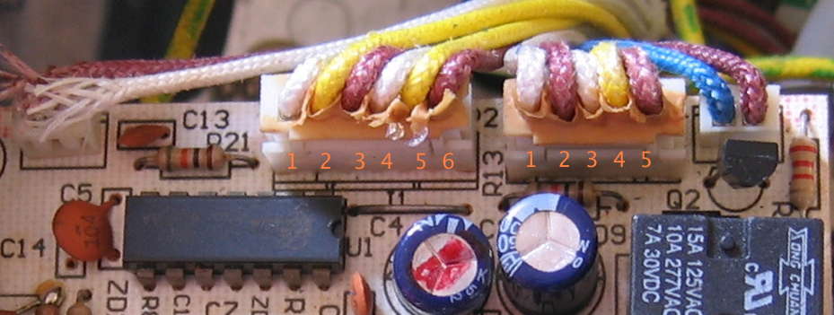
Cross-reference with the official service manual PDF for full harness pinout.
4. V++ Power Supply — The Critical Failure Point
This is the most important section for diagnosing electronic faults on the 800ES. Understanding the V++ supply is the difference between a quick repair and hours of chasing symptoms.
What Is the V++ Supply?
The 800ES does not use a transformer or switch-mode supply for its low-voltage logic rail. Instead, it uses a capacitive dropper (also called a capacitive power supply or X-cap supply):
- Mains AC passes through C1 (the dropper capacitor), which acts as a current-limiting reactance
- R2 provides inrush limiting
- ZD6 (27V, 3W zener) clamps the output to ~27V DC (this is V++)
- C2 (100µF 50V) and C4 (220µF 25V) smooth the V++ rail
- R1A / R1B (120kΩ each) are bleeder resistors across C1 to discharge it when unplugged
- V+ (5V logic rail) is derived from V++ via resistor R24
This design is cheap, compact, and has no mains isolation — but it is critically dependent on C1 maintaining its rated capacitance.
V++ Revision Table
| Revision | Target Voltage | C1 Value | R2 Value | R24 Value | Max I (V++) | Notes |
|---|---|---|---|---|---|---|
| Rev 1 | 240V AU/NZ | 0.82µF | 22Ω | 1.2kΩ 1W | ~62mA | AU production machines |
| Rev 2 | 120V US | 2.2µF | 47Ω | 1.2kΩ 1W | ~100mA | US 800ESXL |
| Rev 3 | 120V US | 1.5µF | 47Ω | 1.5kΩ 2W | ~67mA | Later US revision |
Minimum V++ current required for AU machine operation: ~43mA
⚠️ Do not substitute US-spec capacitor values into an AU machine. A 2.2µF C1 at 240V will overdrive the circuit, overload ZD6, and likely destroy the PCB.
V++ Circuit Diagrams
| Diagram | Link |
|---|---|
| Rev 1 (240V AU) | /img/bes800es/vpp-rev1.svg |
| Rev 2 (120V US) | /img/bes800es/vpp-rev2.svg |
| Rev 3 (120V US) | /img/bes800es/vpp-rev3.svg |
C1 Capacitor Failure — The #1 Fault
Why it fails: Polypropylene X-cap types can lose capacitance over time, especially with heat cycling and age. The 800ES is now 20+ years old — C1 degradation is the single most common cause of electronic misbehaviour.
Symptoms of C1 failure (partial, as capacitance drops):
| C1 Capacitance | V++ Current | Symptom |
|---|---|---|
| 0.82µF (nominal) | ~62mA | Normal operation |
| ~0.6µF | ~45mA | Marginal — may fail under load |
| ~0.5µF or less | <43mA | Dim LEDs, pump stutters or stops when heater is also on |
| Near open circuit | ~0mA | Machine completely dead |
How to test C1:
- Disconnect mains. Discharge C2 and C4 via 10kΩ resistor.
- Desolder C1 from the board.
- Measure capacitance with a capacitance meter.
- Compare against nominal: 0.82µF (Rev 1, AU machines).
- If below ~0.7µF, replace.
Replacement spec (AU Rev 1):
- 0.82µF, X2 rated, 275V AC or higher
- X2 class (mains-connected suppression capacitor)
- Mechanical fit: verify lead spacing against existing cap
Do not substitute a standard electrolytic or film capacitor — C1 must be X2 class as it sits directly across mains.
5. Common Failure Points (Ranked)
#1 — C1 Capacitor (V++ dropper cap) — Ageing/Loss of Capacitance
Frequency: Very common on machines 10+ years old
Symptoms: Intermittent operation, dim LEDs, pump fails when heater is running, machine stops mid-shot
Fix: Measure capacitance out-of-circuit; replace with 0.82µF X2 275V AC if below spec
Reference: Section 4
#2 — Thermostat 96°C — Failed Open
Frequency: Common
Symptoms: Machine powers on, pump runs, but no heat ever reaches temperature; or machine "ready" immediately (if thermostat fails closed — rare)
Fix: Continuity check at room temp (should be closed). Replace thermostat if open.
#3 — Thermostat 140°C — Tripped or Failed Open
Frequency: Moderate
Symptoms: No steam, no hot water; or machine trips off after brief operation
Context: This is the steam/safety thermostat. On some machines it may reset after cooling. If fails open permanently, replace.
Fix: Continuity check. If open at room temp and doesn't reset on cooling, replace.
#4 — Thermal Heat Protector — Blown
Frequency: Moderate (indicates prior overheating event)
Symptoms: Machine completely dead — no response to power button
Fix: Continuity check. One-shot device — must replace. Critically: identify why it blew (blocked thermoblock, failed thermostat allowing runaway heat) before replacing, or it will blow again.
#5 — MOV V1 — Shorted (after surge)
Frequency: Moderate in areas with poor power quality
Symptoms: Machine trips RCD immediately on mains connection, before power button is pressed
Fix: Visual inspection (bulging, blackening). Continuity check — a healthy MOV should not be shorted at room temp. Replace with equivalent varistor.
Note: MOV is present on all production boards but is omitted from the service manual schematic — see Section 9.
#6 — PCB Fuse — Blown
Frequency: Moderate
Symptoms: Machine completely dead
Fix: Continuity check. Always identify root cause (shorted component, pump surge) before replacing fuse.
#7 — SCR Q1 — Leaky or Failed
Frequency: Less common
Symptoms: RCD tripping during operation; pump running without command; machine doesn't pump when commanded
Fix: SCR test (see Section 1). Replace with 2P4M 400V (or 2P6M 600V as upgrade).
#8 — Pump Assembly — Mechanical Failure / Winding Open
Frequency: Less common (pumps are generally reliable)
Symptoms: No water flow, motor hum with no movement, or complete silence when pump commanded
Fix: Resistance test (see Section 1). Confirm mains voltage is reaching pump terminals before condemning pump.
6. Diagnostic Trees
Tree A — Intermittent Operation / Pump Fails When Heater Is On
Machine works sometimes, but pump stops or LEDs dim when heating ─┐
                                                                   │
                                    ┌──────────────────────────────▼──────┐
                                    │ Measure C1 capacitance (out of      │
                                    │ circuit after discharging caps)      │
                                    └──────────┬──────────────────────────┘
                                               │
                          ┌────────────────────┴────────────────────┐
                          ▼                                          ▼
                  C1 < 0.7µF or open                        C1 reads OK (~0.82µF)
                          │                                          │
                          ▼                                          ▼
              Replace C1 with 0.82µF X2               Check V++ rail voltage (~27V)
              275V AC — most likely fix                             │
                                               ┌───────────────────┴───────────────┐
                                               ▼                                   ▼
                                       V++ low or absent                    V++ OK (~27V)
                                               │                                   │
                                               ▼                                   ▼
                                    Check ZD6 zener (27V 3W)          Check RL1 relay contacts
                                    Check R2 (22Ω) for open           Check wiring / connectors
                                    Check C2, C4 ESR                  Check SCR Q1
Tree B — Machine Trips RCD
RCD trips when machine is plugged in ──────────────────────────────┐
                                                                    │
                                    ┌───────────────────────────────▼────┐
                                    │ Does it trip immediately on plug-in │
                                    │ (before power button pressed)?      │
                                    └──────────┬──────────────────────────┘
                                               │
                          ┌────────────────────┴────────────────────┐
                          ▼                                          ▼
                     YES — immediate                         NO — trips during use
                          │                                          │
                          ▼                                          ▼
               Inspect MOV V1 (varistor)              Check SCR Q1 for leakage
               Visual: bulging/blackened?             Check thermoblock insulation
               Continuity: should NOT be shorted      Check pump winding to earth
               Replace if shorted                     Check wiring for chafing
Tree C — No Heat / No Steam
Machine powers on and pumps, but no heat or steam ─────────────────┐
                                                                    │
                                    ┌───────────────────────────────▼────┐
                                    │ Does any heating occur?             │
                                    │ (thermoblock warm to touch?)        │
                                    └──────────┬──────────────────────────┘
                                               │
                          ┌────────────────────┴────────────────────┐
                          ▼                                          ▼
                   No heat at all                         Heats but no steam
                          │                                          │
                          ▼                                          ▼
             Check Thermal Heat Protector          Check Thermostat 140°C:
             (continuity — one-shot fuse)          open at room temp? → replace
                          │                        Check steam wand / valve
                          ▼                        blockage
             Check Thermostat 96°C:
             open at room temp? → replace
                          │
                          ▼
             Check thermoblock element resistance
             (~48Ω for 1200W @ 240V)
             Open = replace thermoblock assembly
7. Official Service Manual & Schematics
Service Manual (PDF)
📄 BES800ES Service Manual (PDF)
The official Breville service manual covers disassembly, reassembly, part numbers (AU/NZ edition), and the circuit schematic. Note the known discrepancies documented in Section 9 before relying on the schematic values.
Hand-Drawn Schematic

Full circuit schematic — refer alongside the service manual PDF.
V++ Power Supply Circuit Diagrams
| Revision | Diagram |
|---|---|
| Rev 1 — 240V AU (C1=0.82µF) |  |
| Rev 2 — 120V US (C1=2.2µF) |  |
| Rev 3 — 120V US (C1=1.5µF) |  |
Connector Pin Diagram
Use this alongside the official service manual to trace harness connections.
Independent Repair Resource
🔗 siber-sonic.com — Breville 800ES Repair Guide:
https://siber-sonic.com/appliance/breville800sm.html
This is the most detailed independent resource available for the 800ES. It includes:
- Full circuit analysis of the V++ capacitive supply
- Component-level schematic with actual measured values
- PCB revision history and gotchas
- Repair case studies
Essential reading before attempting any electronic repair on this machine.
8. Manual & Resource Search Strings
Use these search strings to find additional resources, parts, and community repair threads:
"Breville 800ES" repair
"BES800ES" fault
"Breville 800ESXL" schematic
"TSK-1835A" espresso
"breville espresso capacitor" repair
"800ES intermittent" pump
"breville thermoblock" 800ES replacement
site:siber-sonic.com breville
"800ES/232" PCB
"capacitive power supply espresso"
"C1 capacitor" breville 800
"0.82uF X2" espresso machine
breville espresso "dim LED" fix
"800ES" thermostat replace
breville "15 bar" thermoblock repair
9. Known Quirks & Gotchas
These are documented inconsistencies and failure modes that will catch out anyone relying solely on the service manual.
1. TSK-1835A IC Sticker Falls Off
The main control IC on the 800ES/232 PCB is the TSK-1835A. It has a label sticker on top reading 1835bsaa. This sticker is notorious for detaching over time due to heat cycling and age. If you're looking at a bare IC with no marking, it is almost certainly the TSK-1835A. Do not replace the IC without exhausting all other diagnoses — it is not available as a standalone component.
2. C1 Rated Value vs Actual Board Value
Some third-party documentation and parts lists quote C1 as 1.0µF or other values. The correct Rev 1 AU value is 0.82µF. Always measure the capacitor in circuit to understand what revision you have, and verify by inspecting R2 (22Ω = Rev 1 AU; 47Ω = US revisions).
3. C2 and C4 Values Swapped in Some Service Manual Versions
Some editions of the Breville service manual have C2 and C4 values transposed:
- Correct values: C2 = 100µF 50V, C4 = 220µF 25V
- Some manual versions show these reversed
Always verify actual component markings on the board rather than trusting the schematic values for these caps.
4. RL1 Relay Switches the Line (Active) Side
RL1 switches the Line (L) side of the mains supply to the load — not the Neutral. This is the conventional and safer approach (switching the active wire), but it means the thermoblock, pump, and water valve are still connected to Neutral when RL1 is open. The machine is never fully isolated from mains without disconnecting at the wall.
5. MOV V1 Is Present on All Production Boards But Absent from the Schematic
The surge-suppressing varistor (MOV V1) is fitted across L and N on every production 800ES board. However, it does not appear on the official service manual schematic. If you're tracing RCD faults and find a shorted component that doesn't match the schematic, it is almost certainly the MOV. Replace with an equivalent varistor (check voltage rating and clamping spec).
6. SCR Rating Discrepancy: 2P4M vs 2P6M
- Service manual schematic: specifies 2P6M (600V SCR)
- Actual production boards: fitted with 2P4M (400V SCR)
When replacing Q1, the 2P4M is the correct like-for-like part. The 2P6M is an acceptable upgrade (higher voltage rating, same pinout and current spec). Do not use a lower-rated SCR.
7. Capacitive Supply Has No Mains Isolation — Scope Probe Ground Risk
If using an oscilloscope on this circuit, the circuit is mains-referenced. Connecting a standard oscilloscope probe (with grounded shield) will cause a short circuit. Use only a differential probe or measure on a fully isolated machine via an isolation transformer. This is a common cause of secondary damage during diagnosis.
8. Age-Related Failure Profile
The 800ES entered sale in November 2004 — machines are now over 20 years old. Beyond C1 ageing, expect:
- Dried connector contacts and cracked housings
- Degraded pump capacitors (if pump-start cap is present)
- Hardened seals and O-rings in the thermoblock path
- Scale accumulation in thermoblock (AU tap water)
Descaling is recommended before electronic diagnosis if machine history is unknown.
10. Cross-References
Shared Components with Other Breville Models
| Component | 800ES Part | Potentially Shared With | Notes |
|---|---|---|---|
| Thermostat 96°C | (see service manual) | BES870, Café Roma, other thermoblock machines | Verify voltage/temp rating match exactly |
| Thermostat 140°C | (see service manual) | Similar Breville thermoblock range | Verify before substituting |
| Pump Assembly | AU/NZ spec | Other 15-bar AU Breville espresso machines | Must match voltage/Hz spec |
| Water Valve/Solenoid | (see manual) | Common across Breville thermoblock range | Verify coil voltage |
| X2 Capacitor C1 | 0.82µF X2 275V AC | Generic component — any brand | X2 class mandatory |
| SCR Q1 | 2P4M (TO-92) | Generic component | 2P6M is upgrade-compatible |
| MOV V1 | Varistor, L-N | Generic component | Match clamping voltage to mains spec |
Architectural Comparison: 800ES vs BES870 (for part cross-referencing)
| Architecture Point | 800ES | BES870 | Cross-compatibility |
|---|---|---|---|
| Thermoblock | Yes | Yes | Different physical format — not interchangeable |
| Pump | 15 bar vibration pump | 15 bar vibration pump | May share pump body — verify connector and voltage |
| PCBs | 3 discrete PCBs | Integrated assembly | Not interchangeable |
| Thermostats | Bimetallic, clip-on | NTC thermistors (different sensing method) | Not interchangeable |
| Housing | 800ES form factor | BES870 form factor | No shared housing parts |
Dossier compiled from: Breville 800ES Official Service Manual (AU/NZ), siber-sonic.com independent repair analysis (https://siber-sonic.com/appliance/breville800sm.html), and embedded schematics.
Last updated: March 2026